
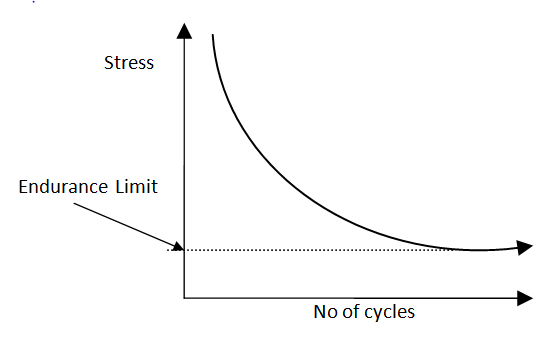
Cyclic load means varying or alternating mechanical or thermal load. Below is the graph which represents fluctuating stresses due to varying loads.
Failure depends upon the number of cycles at a given range of stress rather than the total time under load. When the stress level falls below a certain limit, the number of allowable cycles is said to be infinite. This value of stress is known as the endurance or fatigue limit and indicates that a very large number of cycles could occur.
The behaviour of metal under fatigue conditions is a lot different from normal stress-strain relationships. Each fatigue cycle depending upon the stress range damages the life cycle of the equipment. If there are multiple different cycles, damage accumulates during each cycle of loading, thus reducing the total life.
Loading develops localized stresses at the location of discontinuities and stress risers, which results in micro-cracks and the cyclic nature of loading causes cracks to begin and propagate. Design plays a major role in eliminating or reducing regions of stress risers and discontinuities. It is common to have the design life of a vessel cut in half by poor design details. A good design minimizes the stress risers and discontinuities by avoiding the following;
- Avoiding fillet welds if possible,
- avoiding reinforcement pads,
- avoiding partial penetration welds,
- avoiding abrupt changes in thickness,
- avoiding sharp edges etc.
Fabrication tolerances also play equal importance. Mostly, normal tolerances for vessels are not adequate. The ASME tolerance for out of roundness of 1% is not always acceptable. Peaking and banding tolerances may need to be much lower than the Code allows. Offsets between plates should be carefully controlled.
Additional factors for carbon steel vessels in cyclic service:
- Vessels shall be PWHT
- Material to be normalized
- Material to be fine grain practice (7 or finer)
- Plate material shall be 100% UT examined
- All welds full penetration
- All main seams ground flush
- All attachment welds, internal or external, shall be ground smooth or contoured
The ASME Code, Section VIII, Division 1, does not provide a procedure for the design of vessels in cyclic service. However, ASME Section VIII, Division 2 has detailed procedures detailed fatigue analysis. It is acceptable to built and stamp a vessel as per SEC VIII Div 1 and do the fatigue analysis as per SEC VIII Div 2. SEC VIII Div 1 vessel cannot be exempted from fatigue simply because the code does not cover it. Fatigue analysis has to be done as per ASME SEC VIII Div 2, Appendix 5. Permissible design stress based on Div 2 is called Fatigue strength of the material.
The code provides design fatigue strength curves Sa-N. Sa is the maximum alternating stress amplitude, which is plotted against the maximum permissible number of cycles N, as shown below
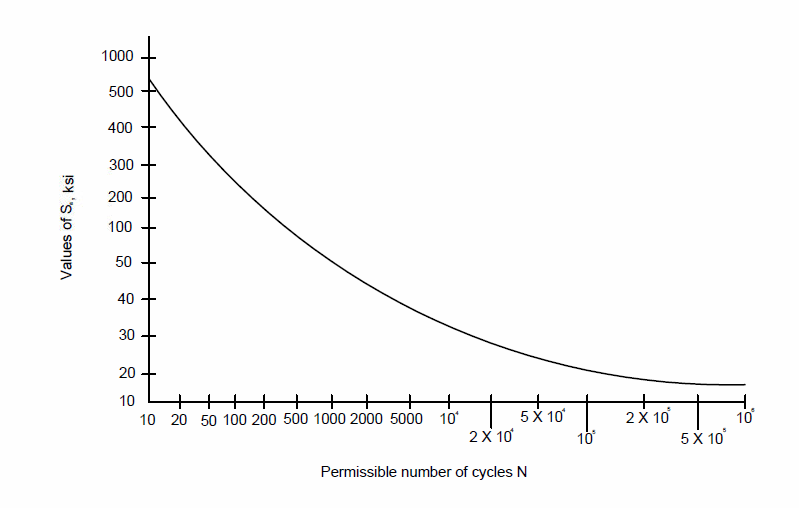
For fatigue analysis, only the stresses which vary during the service life needs to be considered. Stresses due to static/constant loads, which do not vary during an operating cycle, need not be considered since they are taken as mean stresses and their effect was included in the fatigue design curve by modifying technique.
ASME SEC VIII Div 2 procedure for fatigue
Screening criteria:
Not every cyclic service loading could shorten the design life of a vessel and hence, not every vessel in cyclic service requires a detailed fatigue analysis. Code acknowledges this and provides screening procedures to determine if a vessel requires fatigue analysis or not.
Following screening criteria for fatigue evaluation has been provided in code:
Method 1:
Experience with comparable equipment operating in similar conditions – If a successful experience of equipment in similar conditions subjected to a similar loading histogram is available.
Method 2: Fatigue analysis screening method A –
Applicable for material with tensile strength lower than or equal to 552 MPa. It is simpler than method B and also more conservative.
The addition of different cycles should be less than as given in the below table.
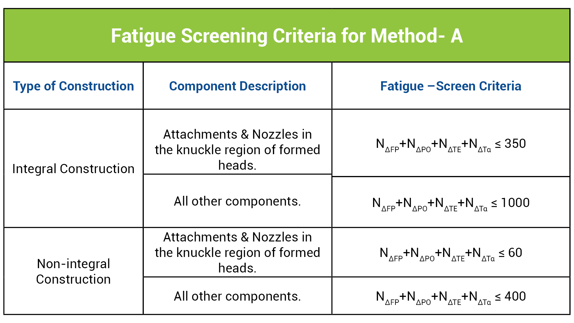
Where,
N∆FP= No of full-range pressure cycles including start-up and shutdown
N∆FO=No of pressure cycles in which the range of pressure variation exceed 20% of design pressure for an integral part and 15 % of design pressure for non-integral parts
N∆TE= No of changes in metal temperature difference, multiplied with factor as indicated in code
N∆Tα= No of cycles for components having welds between materials with different thermal coefficients that cause the value (α1-α2)∆T to exceed 0.00034
If the number of cycles meets screening criteria, then fatigue analysis is not required.
Method 3: Fatigue analysis screening method B –
This method can be used for all materials. It is not a simple, single procedure as is outlined in method A. Six of the steps require stress calculations, and not satisfying any of the six calculation steps results in a requirement to perform a detailed fatigue analysis. A detailed discussion of method B is excluded from the scope of this paper.
0 Comments